
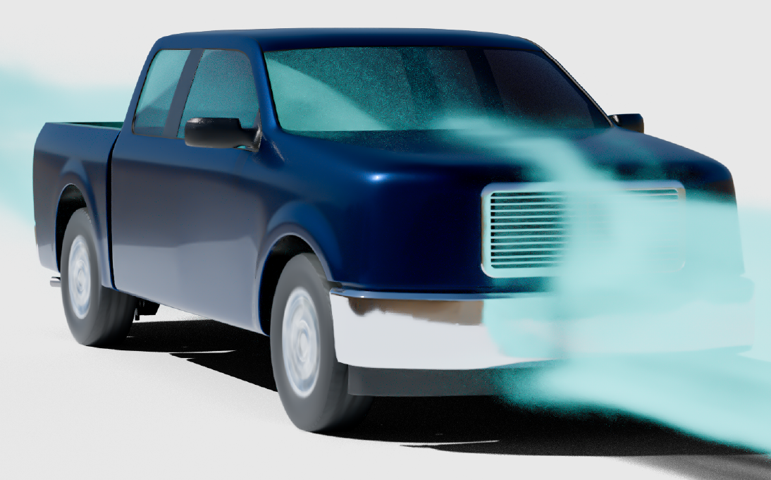
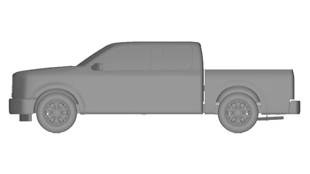
The General Truck Utility (GTU) model, a public domain benchmark developed by Ford Motor Company, provides the automotive industry with a standardized, realistic platform for aerodynamic research [1]. This article is the second installment in the HELYX and ELEMENTS Validation Series, a collection of benchmarks showcasing the technical capabilities and accuracy of our open-source CFD products across a range of applications and physics.
CFD validation is essential for ensuring reliable aerodynamic predictions in automotive applications. In this study, ELEMENTS is used to simulate the GTU benchmark vehicle model and compare aerodynamic results against experimental reference data. The work demonstrates how open-source CFD can deliver accurate external automotive aerodynamics simulations for automotive development workflows.
Here, we demonstrate how a GTU model simulation using ENGYS’ open-source CFD software ELEMENTS accurately predicts key aerodynamic forces while balancing computational cost.
The Challenge: Balancing Accuracy and Cost in Vehicle Aerodynamics
For automotive aerodynamicists, the central engineering challenge is achieving high-fidelity simulation results within the practical constraints of project timelines and computational budgets. Predicting aerodynamic forces like drag on a complex vehicle geometry requires a robust workflow, but extensive manual configuration for each case can be time-consuming and introduce user-dependent variability.
Engineers need a reliable method that streamlines the CFD process and offers a predictable trade-off between simulation accuracy and turnaround time, particularly in workflows involving car design and aerodynamics.
How ELEMENTS Aero Wizard Streamlines GTU Model Simulation
ELEMENTS addresses this challenge with its integrated Aero Wizard, which provides pre-configured, validated CFD simulation templates. These templates encapsulate ENGYS’ best practices for external automotive aerodynamics, allowing users to achieve reliable and consistent results without requiring deep manual setup for every simulation.
This approach represents a form of CFD workflow automation, streamlining the entire process from meshing to post-processing in one go.
The GTU benchmark model is widely used in the CFD community for validating automotive aerodynamic simulations due to its well-documented experimental datasets and reproducible benchmark methodology.
This study directly compares two of these templates applied to the GTU model 7 (long cab, short box configuration):
- Open-Road_ELEMENTS_Defaults: A template optimized for rapid turnaround and baseline analysis.
- Open-Road_ELEMENTS_HighFidelity: A template designed for higher accuracy, with more refined mesh settings and longer time-averaging.
Simulation Setup: Comparing Default vs. High-Fidelity Templates
The simulation setup for both cases was managed entirely through the Aero Wizard, with the primary differences lying in the mesh resolution and simulation runtime.
Meshing Strategy and Computational Domain
A virtual wind tunnel was created using a box domain measuring 105 m in length, 110 m in width, and 49.7 m in height.
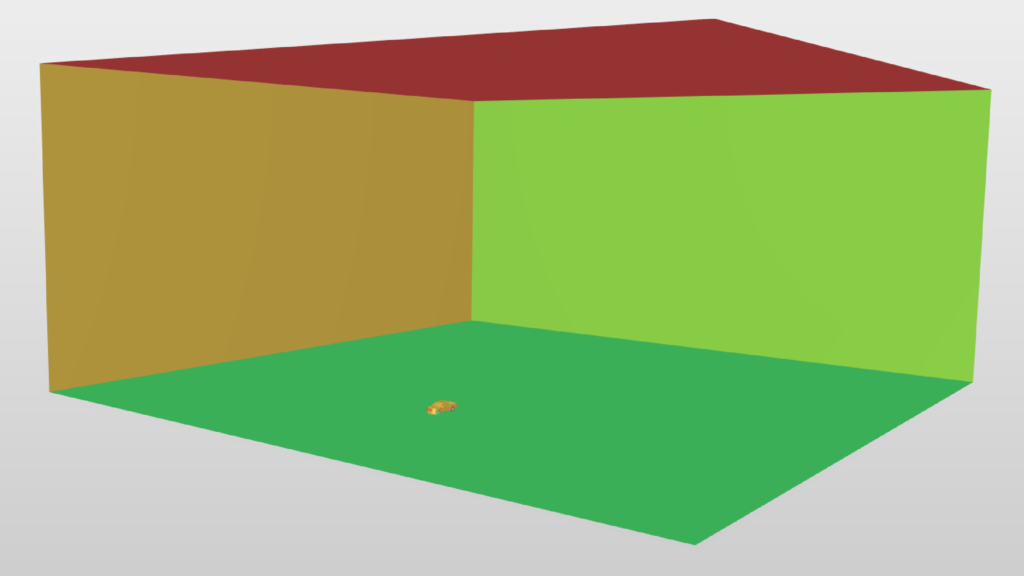
The computational setup was designed to reproduce the benchmark conditions used in published experimental studies, enabling direct comparison against validated aerodynamic reference data.
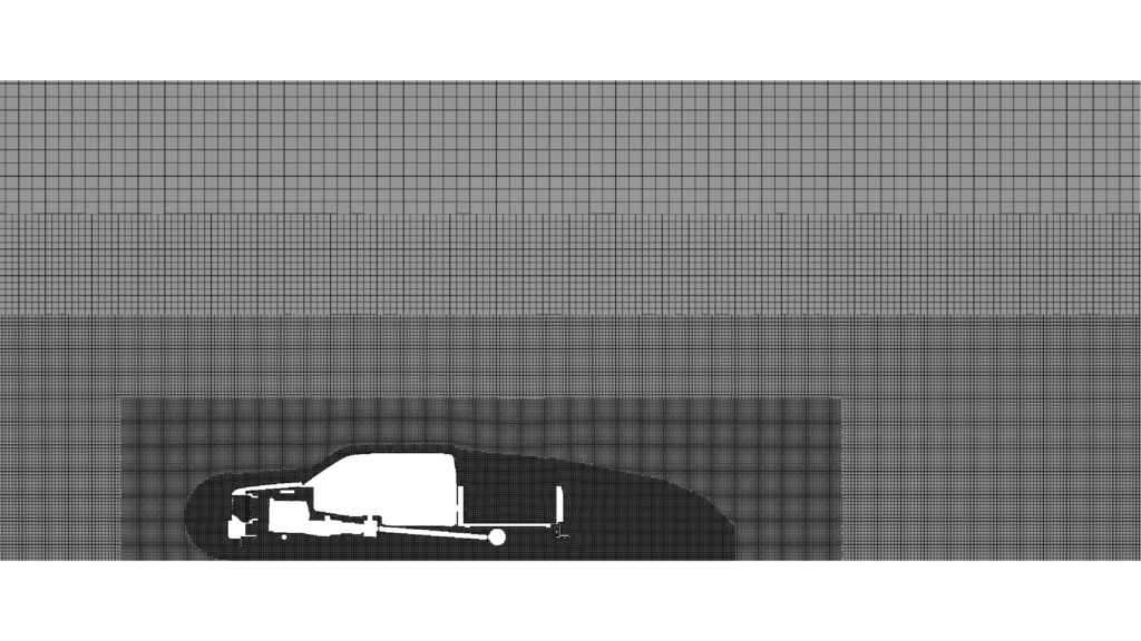
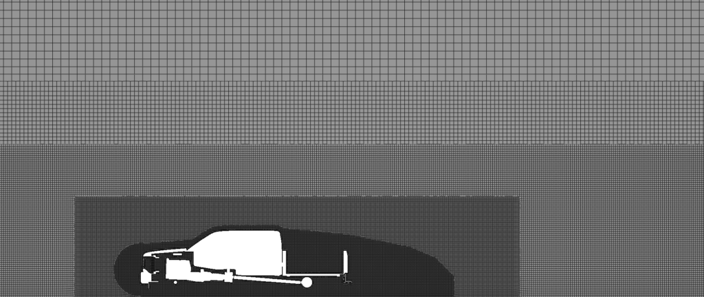
The core distinction between the ‘Default’ and ‘High Fidelity’ templates is the meshing strategy. The High Fidelity setup employs a significantly higher level of surface refinement on key aerodynamic features, including the front grill, side mirrors, windows, wheels, and areas with high surface curvature.
This targeted refinement, powered by advanced hex-dominant meshing, is designed to capture complex flow phenomena more accurately.
The mesh refinement strategy focused on critical aerodynamic regions including the underbody, wheel wake interaction zones, and rear recirculation structures to ensure accurate aerodynamic drag prediction and wake development.
The resulting computational grid sizes were:
- Default: 31,053,071 hexa-dominant cells.
- High Fidelity: 85,097,789 hexa-dominant cells.
The difference in mesh density is visible in both the surface mesh and the volume mesh cross-sections, with the ‘High Fidelity’ case showing finer cells around the vehicle body and in its wake.
Physics, Boundary Conditions, and Solver Settings
Both simulations modeled isothermal, turbulent, incompressible transient flow. The setup utilized open-source CFD based on a pressure-based solver with the PIMPLE algorithm to sequentially solve the conservation equations of mass and momentum.
The DDES Spalart-Allmaras model was selected for turbulence modeling. This hybrid RANS-LES approach is well-suited for resolving the large-scale turbulent structures in the vehicle’s wake, a common practice for complex external automotive aerodynamics [3].
Key boundary conditions included:
- Inlet: A uniform flow speed of 38.89 m/s.
- Floor: A “moving wall” boundary condition to simulate road movement.
- Wheels: A “Wheel Motion” boundary condition to replicate tire rotation.
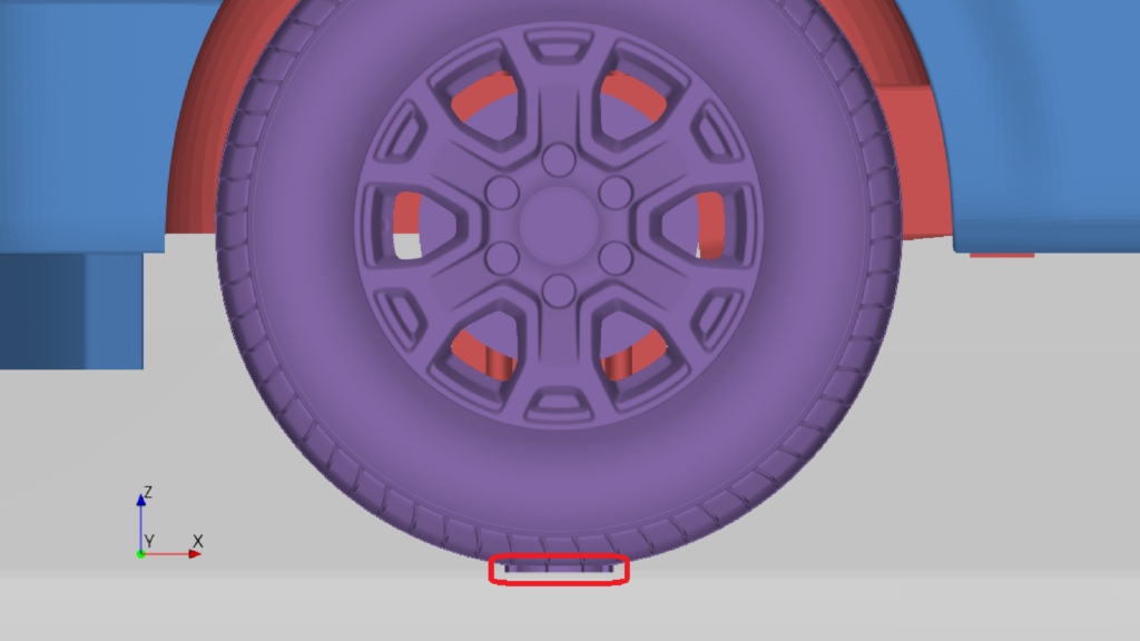
- Contact Patch: Four 1 mm high patches were defined to accurately resolve the critical wheel-floor interface.
Both simulations were run on an in-house HPC cluster using 192 processors using an AMD EPYC 7351 (Naples) 16-Core.
Results Analysis: A Deep Dive into Aerodynamic Performance
The primary objective was to validate the drag coefficient prediction and assess the performance trade-off between the two Aero Wizard templates.
Validating Drag and Lift Coefficients Against Experimental Data
The validation process focused on quantitative comparison against published experimental reference data, including aerodynamic drag prediction, wake behaviour, and pressure distribution correlation.
The time histories for drag (CD) and lift (CL) coefficients demonstrate that both simulations reached a statistically steady state, allowing for reliable time-averaging.
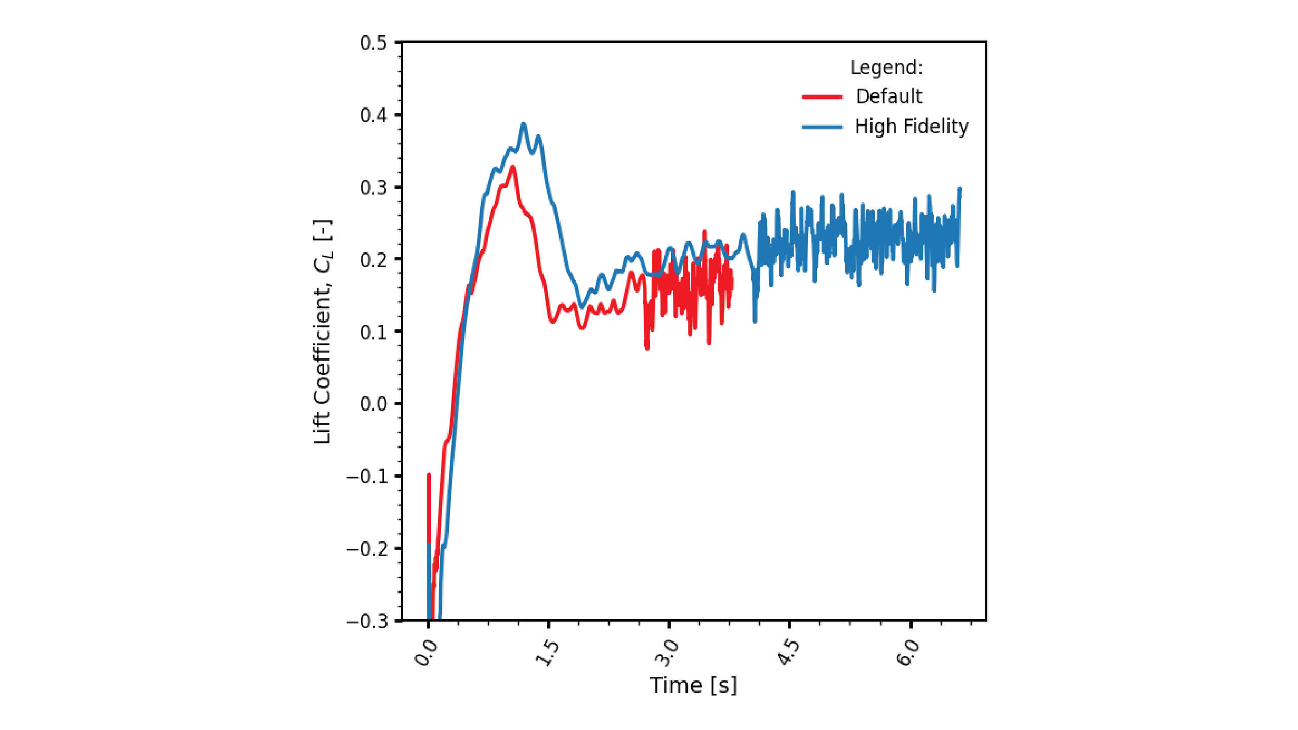
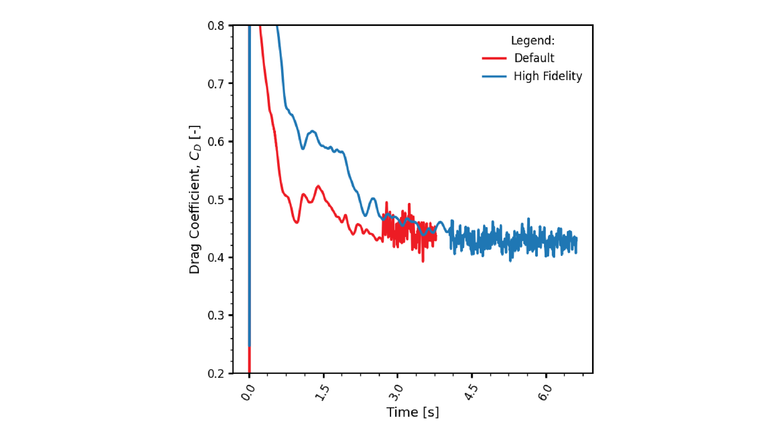
The final force coefficients, when compared against experimental data from wind tunnel testing [2], highlight the effectiveness of both templates and align with methodologies discussed in benchmarking CFD for external aerodynamics.
| Case | Drag Coeff. (CD) | Lift Coeff. (CL) | Run Time |
|---|---|---|---|
| Default | 0.443 | 0.162 | 3h 09m |
| High Fidelity | 0.427 | 0.228 | 4h 28m |
| Experiment | 0.404 | 0.196 | N/A |
The benchmark comparison demonstrates strong agreement between simulation and experimental measurements, validating the numerical setup and modelling strategy used in ELEMENTS.
The ‘High Fidelity’ simulation predicted a drag coefficient of 0.427, which is within 5.7% of the experimental value. This excellent agreement comes with a computational cost of 4 hours and 28 minutes. The ‘Default’ simulation, while showing a larger deviation of 9.7% (CD of 0.443), completed in just 3 hours and 9 minutes, demonstrating its value for rapid design iterations.
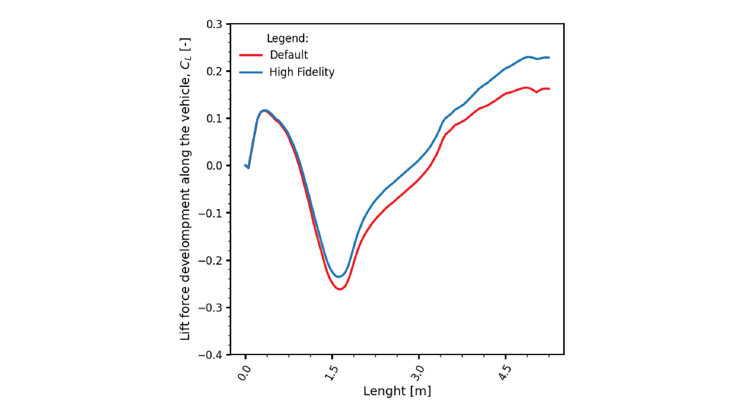
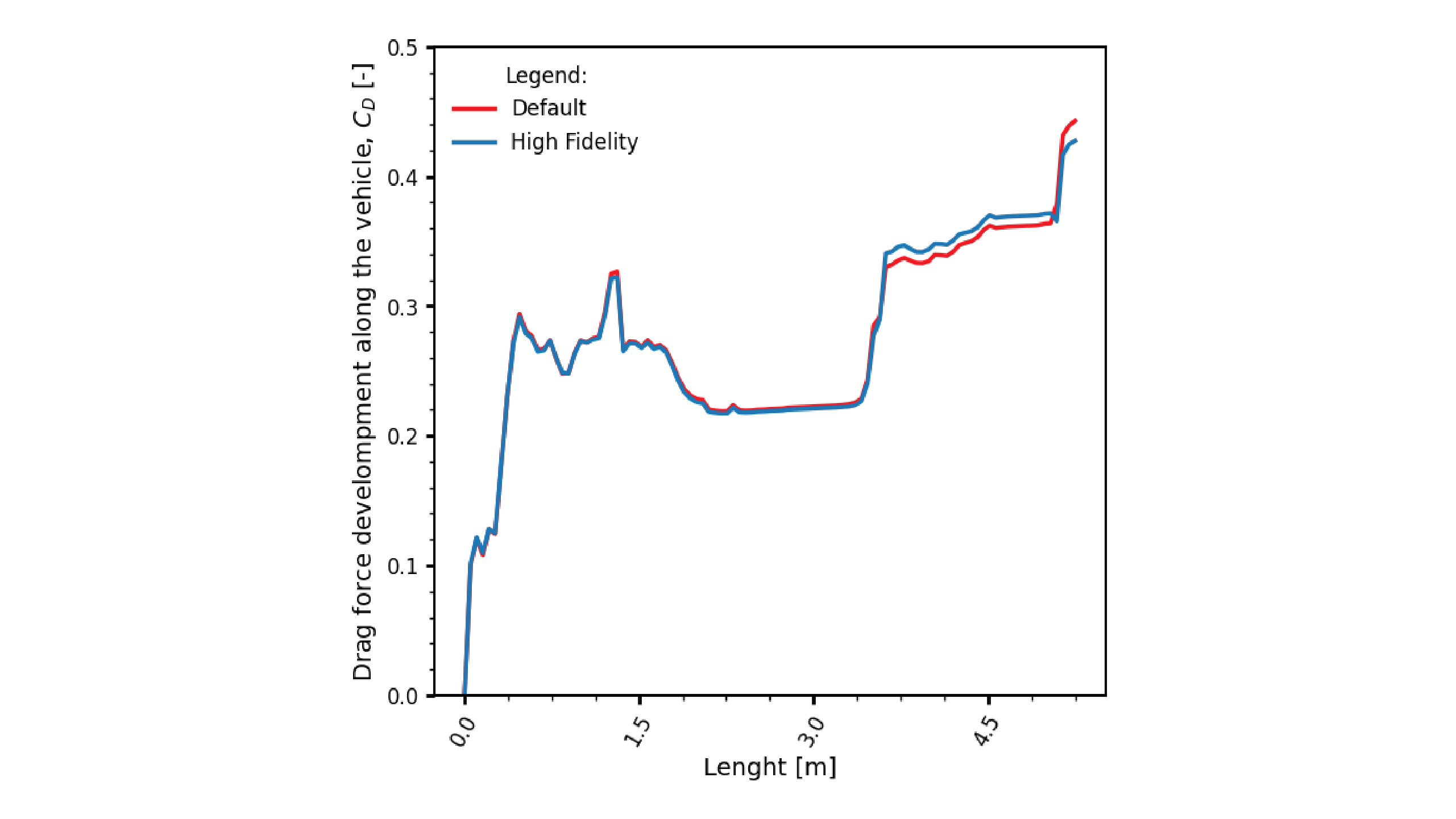
The development of drag and lift forces along the length of the vehicle also shows good correlation between the two simulation levels, with the primary deviations occurring around the cabin and bed areas.
Visualizing Flow Structures and Surface Pressure
Beyond integral forces, a robust CFD validation requires a qualitative comparison of the flow field. The higher mesh resolution of the ‘High Fidelity’ case allows it to capture finer details in the vehicle’s wake and boundary layer.
The simulations capture key aerodynamic phenomena including front stagnation regions, rear wake separation, roof acceleration effects, and wheel-induced vortex structures commonly observed in vehicle aerodynamics with CFD simulation.
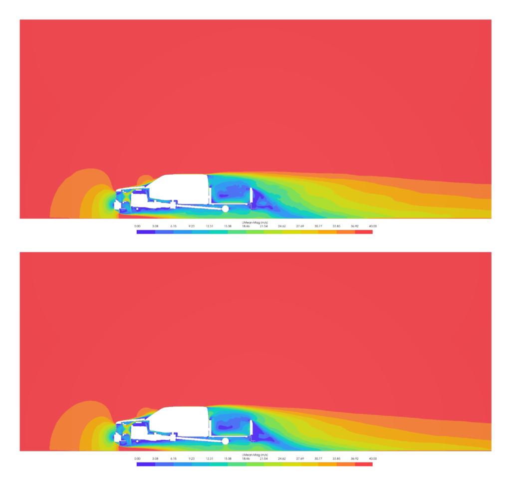
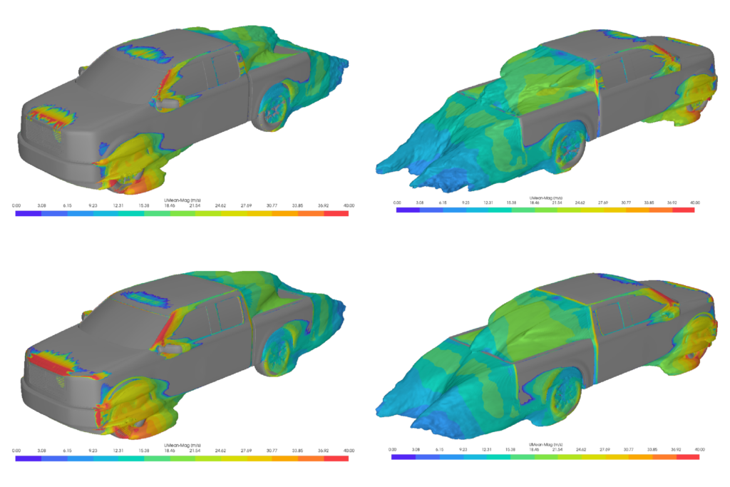
The mean velocity distribution in the vehicle’s wake is more sharply resolved in the High Fidelity case.
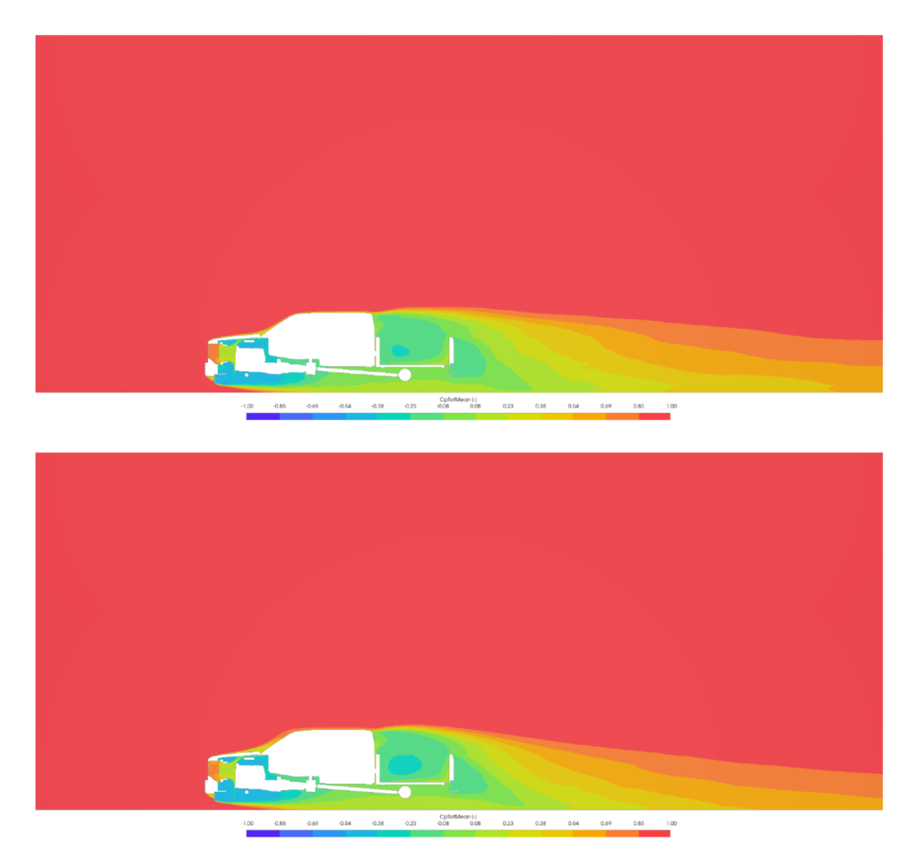
Similarly, the mean total pressure coefficient contours show a more detailed and less diffuse wake structure for the High Fidelity simulation, indicating a better preservation of turbulent structures.
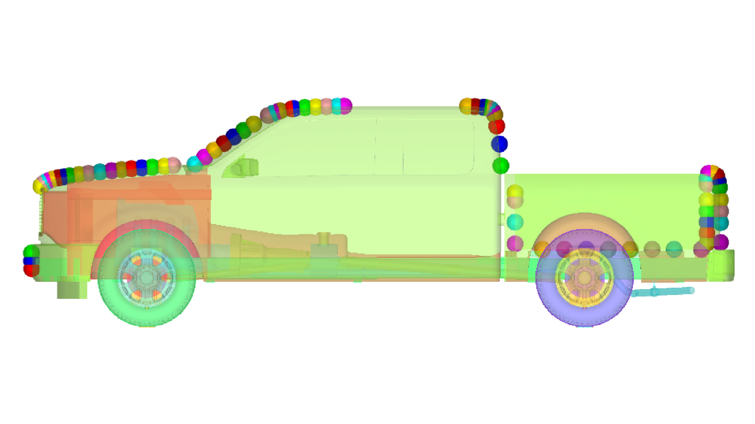
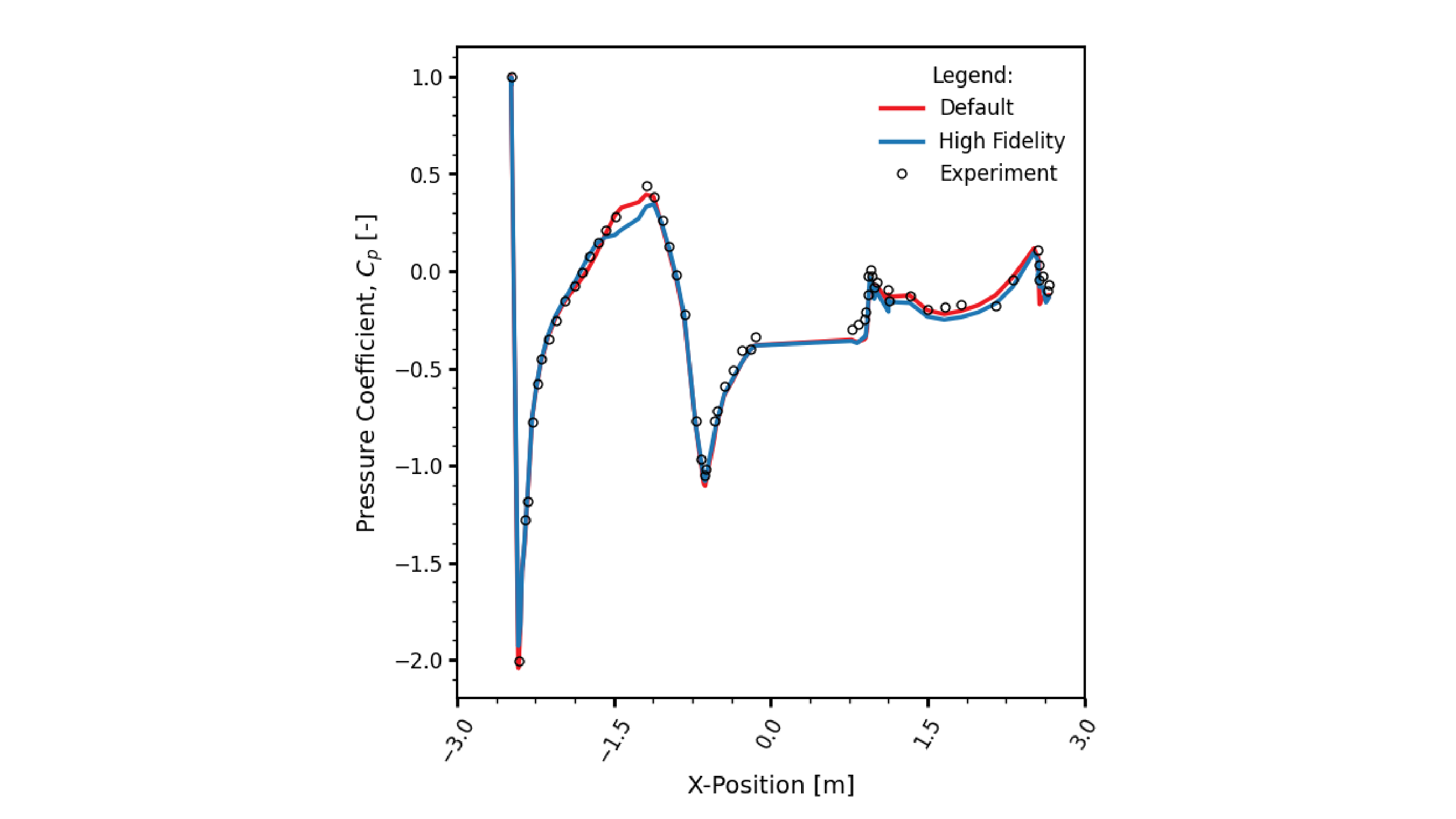
Pressure distribution along the vehicle’s upperbody centerline shows that both simulations capture the key pressure peaks and troughs, though the High Fidelity results align more closely with experimental trends in critical regions like the windshield and roof.
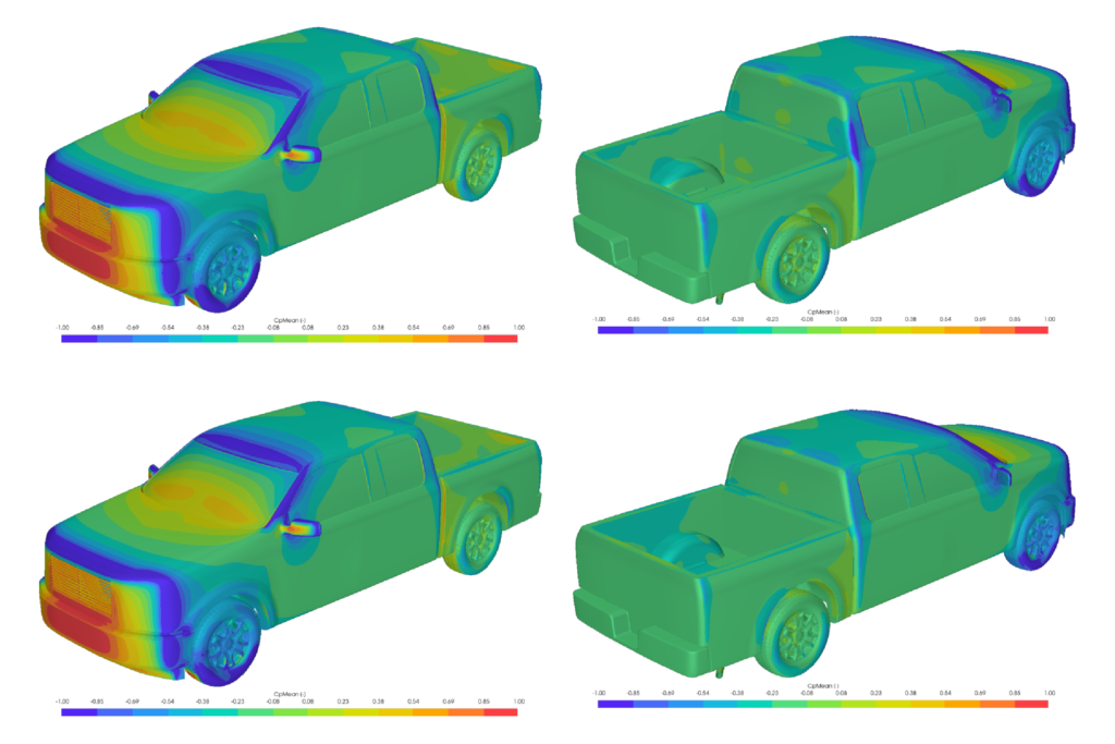
Surface plots of pressure, near-wall velocity, and wall shear stress further illustrate the impact of mesh refinement, with the High Fidelity case providing a crisper resolution of flow features on the vehicle body.
The resulting flow structures show strong consistency with published benchmark datasets and experimental observations, reinforcing the reliability of the CFD methodology applied in this study.
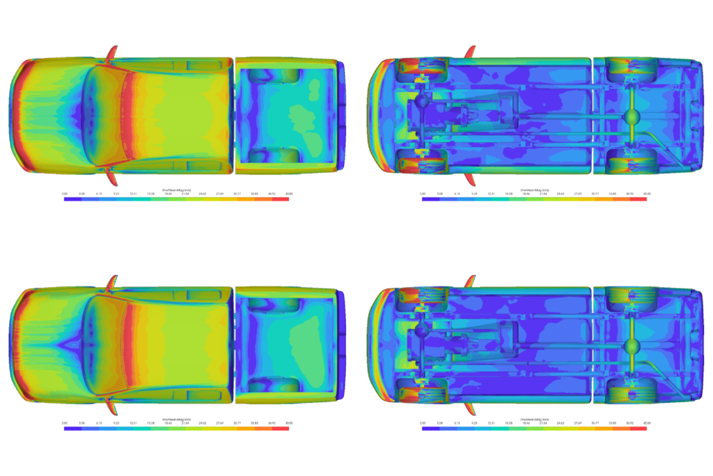
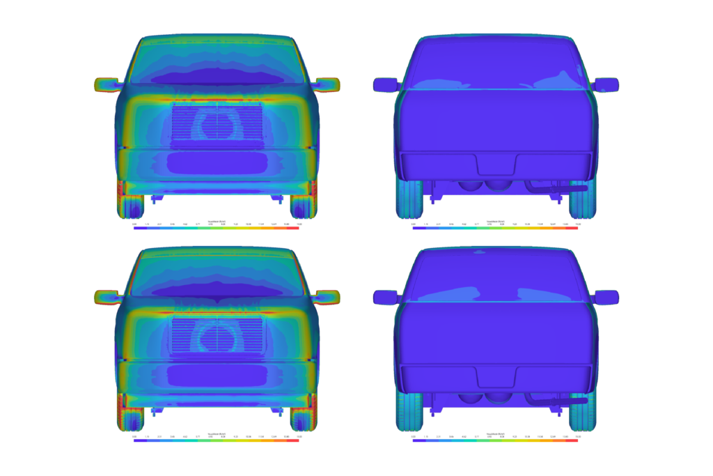
The wake structure, visualized by an iso-surface of zero total pressure, is also more defined in the High Fidelity simulation, which is crucial for understanding sources of aerodynamic drag.
Making Informed Decisions with Validated CFD
This GTU model simulation demonstrates that ELEMENTS provides automotive engineers with a validated, efficient, and flexible workflow for tackling complex external aerodynamics. The Aero Wizard templates offer a highly flexible custom and consistent setup of a simulation, and a powerful solution to the perpetual trade-off between accuracy and computational cost.
The ‘High Fidelity’ template delivers results within 5.7% of experimental drag data for a highly complex geometry, making it a reliable choice for final design validation. The ‘Default’ template, while less accurate, provides valuable aerodynamic insights in a fraction of the time, empowering rapid design exploration. This flexibility allows engineering teams to make informed decisions, applying the appropriate level of fidelity for the specific needs of their project stage.
By combining validated methodologies with flexible open-source CFD workflows, ELEMENTS enables scalable aerodynamic simulation for automotive engineering applications, including emerging approaches involving AI in automotive aerodynamics.
This study highlights the capability of ELEMENTS to deliver engineering-grade accuracy for external aerodynamics CFD validation and automotive benchmark simulations.
References
[1] Woodiga S., Gowda S., Ramsing A., D’Souza J. ‘The GTU: A New Realistic Generic Pickup Truck and SUV Model’. In: SAE International Journal of Advances and Current Practices in Mobility 2.4 (Apr. 2020), pp. 1986–1998. URL: https://www.sae.org/content/2020-01-0664
[2] Howard K. et al. ‘A Detailed Aerodynamics Investigation of Three Variants of the Generic Truck Utility’. In: SAE International Journal of Advances and Current Practices in Mobility (Apr. 2021). URL: https://www.sae.org/content/2021-01-0950
[3] Revell A., Ashton N. ‘Comparison or RANS and DES Methods for the DrivAer Automotive Body’. In: SAE Technical Paper 2015-01-1538 (2015).