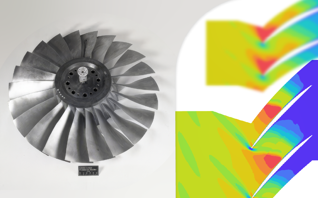
For engineers in the aerospace and power generation sectors, the NASA Rotor 67 is one of the most widely used benchmarks for turbomachinery CFD validation. First documented in a seminal 1989 NASA technical paper1, this low-aspect-ratio, transonic, axial-flow fan rotor is a demanding test case for CFD codes, involving high rotational speeds, complex shock wave structures and significant air compressibility effects. Accurately predicting its performance is a direct indicator of any CFD solver’s capability for industrial-scale turbomachinery applications.
The study presented herein details a comprehensive NASA Rotor 67 CFD validation using HELYX, ENGYS’ general purpose, open-source CFD software. The goal is to demonstrate the accuracy and efficiency of HELYX in replicating the complete experimental performance map published in the NASA Technical Paper 2879, which includes total pressure ratio, efficiency and detailed local flow phenomena.
The 22-blade rotor was designed to operate at a nominal rotational speed of 16,043 rpm, delivering a pressure ratio of 1.63, mass flow rate of 33.25 kg/s, and inlet tip relative Mach number of 1.38. Accurately predicting the fan’s performance across the full operating range, from choke to near-stall conditions, requires a CFD tool that can robustly handle transonic flows and precisely capture boundary layer phenomena. This makes the NASA Rotor 67 an essential CFD validation case for engineers in the aerospace and power generation sectors.
NASA Rotor 67 CFD Simulation Setup in HELYX
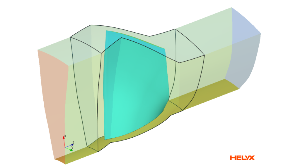
To validate the capabilities of HELYX, a numerical study was conducted to replicate the experimental conditions of the NASA Rotor 67 rotor-only configuration. To ensure computational efficiency, the simulation was limited to a single blade passage, leveraging periodic boundary conditions to avoid modelling the full 360-degree rotor assembly. This approach is standard practice in CFD and allows for a detailed mesh resolution without incurring prohibitive computational costs.
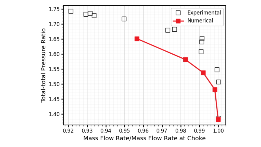
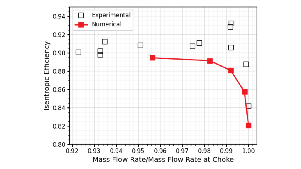
The objective was to compare key performance indicators — namely the total-to-total pressure ratio and isentropic efficiency — from the HELYX simulation directly against the measured values published in the NASA Technical Paper 2879.
Meshing Strategy and Boundary Conditions
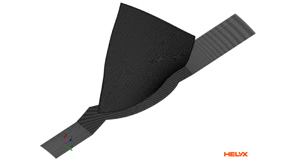
A high-quality computational grid is fundamental to achieve accurate CFD results. Using the automatic hex-dominant meshing algorithm available in HELYX, a mesh of 2.6 million cells was generated for the single-blade passage of the NASA Rotor 67 model.
To accurately resolve the flow near the blade, hub and shroud surfaces, a minimum of 6 near-wall layers were employed to achieve a maximum y+ value of 60, thus providing sufficient local grid resolution for the k-ω SST turbulence model and automatic wall function employed to capture the boundary layer behaviour in the simulations.
The boundary conditions were set to mirror the experimental setup:
- Inlet: a total pressure boundary condition was defined to match atmospheric conditions.
- Outlet: a static pressure condition was applied and varied across multiple simulations (from 100,000 Pa to 127,150 Pa) to generate the compressor’s performance map and capture different operating points.
- Periodicity: Cyclic Arbitrary Mesh Interface (AMI) boundaries were used on the periodic faces of the single-passage domain, ensuring seamless data transfer and representing the full annular cascade.
Solver Settings and Physical Models for Transonic Flows
All simulations of the NASA Rotor 67 were performed in steady-state conditions. The pressure-based HELYX-Coupled solver was selected for its robustness and efficiency in handling compressible, high-speed flows. In this block-coupled solver the momentum and pressure equations are solved in a single matrix, leading to improved performance and faster solution convergence rates.
Other key physics modelled included:
- Rotation: a Multiple Reference Frame (MRF) approach was used to approximate the rotor’s motion as a momentum source term.
- Turbulence: the industry-standard k-ω SST turbulence model with an automatic (all y+) wall function was chosen for its proven accuracy in predicting flow separation and adverse pressure gradients common in turbomachinery.
Results: Validating HELYX Against Experimental Data
The numerical results of the the NASA Rotor 67 obtained using HELYX showed excellent agreement with the available experimental data across multiple key performance metrics. This validates the proposed CFD workflow for turbomachinery applications in HELYX, including meshing, setup, solving and post-processing.
Pressure Ratio and Efficiency Performance Maps
The predicted total-to-total pressure ratio curve closely follows the experimental data across the whole range of flow rates, correctly capturing the characteristics trend and the onset of stall. This demonstrates the block coupled solver’s ability to model the flow dynamics and loss mechanisms within the rotor under steady-state conditions, although the use of fully transient simulations (not tested here) could deliver even more accurate results.
Similarly, the isentropic efficiency curve predicted by HELYX also aligns well with the experimental measurements. The simulation accurately identifies the peak efficiency operating point within 1% or 2% of the experiments, and captures the efficiency roll-off towards both choke and stall conditions.
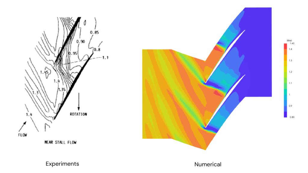
Local Flow Physics: Mach Number Comparison
Beyond validating bulk performance metrics, it is also crucial to confirm that the CFD simulation accurately captures the detailed local flow physics. The original NASA study used non-intrusive laser anemometry to measure flow-field properties, providing an excellent dataset for comparison.
The relative Mach number contours at 10% span from the hub show that HELYX correctly predicts the location and strength of the shock wave at both near-peak-efficiency and near-stall conditions. The flow structures identified in the CFD, including the acceleration around the leading edge and the subsequent shock-induced deceleration, show a strong qualitative and quantitative match with the experimental data.
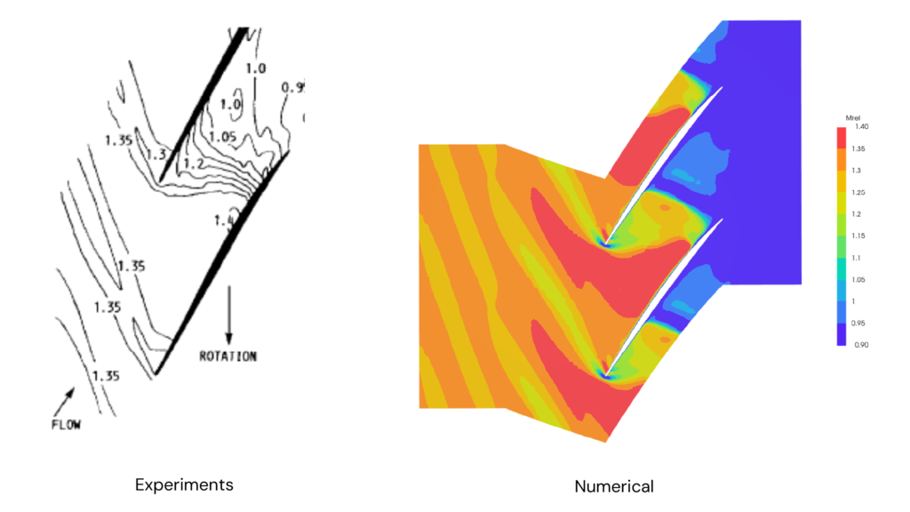
This level of detail is critical for engineers looking to understand phenomena like shock-boundary layer interaction, which can be a primary driver of performance losses and stall inception.
Conclusion: High-Fidelity Turbomachinery CFD Validation with HELYX
The excellent agreement between HELYX simulations and the experimental data for the challenging NASA Rotor 67 benchmark confirms the software’s ability to capture high-fidelity flow phenomena for turbomachinery design and analysis. The combination of its robust pressure-based coupled solver, efficient hex-dominant meshing and comprehensive physics library provides engineers with a reliable and accurate CFD workflow for predicting the performance of transonic axial compressor stages and other complex rotating machinery.

References
- Strazisar A.J, Wood J.R, Hathaway M.D, Suder K.L (1989). Laser Anemometer Measurements in a Transonic Axial-Flow Fan Rotor. NASA Technical Paper 2879. ↩︎