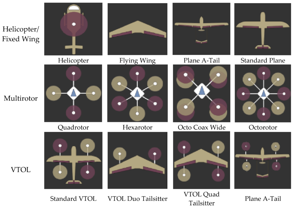
From hand-sized nano drones to 18 metre wingspan military UAVs [1], the endless applications of modern drones have led to an abundance of configurations, ranging from single rotor and multirotor to fixed wing and fixed wing hybrid VTOLs (Vertical Take Off and Landing). However, each comes with its own aerodynamic challenges, that need to be overcome with intuitive design and simulation to achieve aerodynamic efficiency.
The aerodynamic challenges of different drone types
Fixed-wing drones generate lift via the pressure difference between the upper and lower surface of the wings, while thrust is provided by horizontal jet engines or motor driven propellors. The shape of the wings determines the lift, drag, stability and balance of the drone and therefore vary from straight wings, tapered wings, swept back wings and delta wings depending on the speed of flight and the application. Improving the lift-to-drag ratio is typically the main objective for optimisation, as is the effectiveness of control surfaces.
Multirotor drones, on the other hand, generate lift and thrust via the rotation of multiple rotors but are inherently unstable. Therefore, a control system is required to constantly monitor the orientation of the drone, adjusting the speed of each rotor to change yaw, pitch and roll. Understanding the aerodynamic interaction of the various rotors with each other and the body, especially during manoeuvring, is essential to design such a control system.
VTOLs combine the characteristics of both fixed-wing and multirotor drones. Using rotors to generate lift and thrust during vertical flight, transitioning to fixed wings for lift and tilted rotors for thrust in horizontal flight. Aerodynamic optimization is especially complex for VTOLs, as they must balance the competing requirements of fixed-wing and multirotor flight characteristics.
To accurately simulate this vast array of drone types in Computational Fluid Dynamics (CFD) requires a deep understanding of boundary conditions, interaction of multiple rotating elements, as well as stability and drag characteristics of subsonic flows.
‘7 out of 10 Formula 1 teams use our open-source CFD solution HELYX, proving its capabilities for simulating both incompressible and compressible flows at low Mach numbers,’ highlights Thomas Schumacher, Director of Engineering at ENGYS. ‘If you turn the front and rear wings of an F1 car upside down, you get a wing that generates lift instead of downforce. So, as we have already developed an efficient solver for this type of applications with accurate models and automatic meshing in HELYX, we wanted to see how our software could be utilised in the UAV industry too.’
‘But we don’t like entering new markets with unsubstantiated claims, even though we have a lot of aerospace expertise within ENGYS,’ continues Schumacher. ‘So, first we wanted to prove HELYX can accurately simulate drone CFD through several case studies, which is where we came across the fascinating JRM-02XC40 project developed by AeroJTP.’
Case study: CFD of the JRM-02XC40 RC jet
AeroJTP is a collaboration between aircraft engineer and composite specialist René Rosentraeger and industrial designer Marc Veenendaal. Together they develop models of 3D printed RC jets that customers can purchase online, 3D print and build themselves.
‘Our designs are not just scaled down versions of actual aircraft,’ explains Marc Veenendaal, Co-Founder at AeroJTP. ‘We take inspiration from fighter jets but develop unique models using NACA aerofoil profiles that we know will work for particular scenarios. We were the first to create a successful VTOL RC jet using a quadcopter arrangement and it was this model that sparked the idea for the JRM-02XC40.’
The JRM-02XC40 model
The JRM-02XC40 was initially based off the Grumman X-29 and Sukhoi Su-47 Berkut featuring a forward swept wing which allows flight at high angles of attack without stalling. René and Marc decided to adapt this design to make an X wing drone, with a thick middle body to facilitate two fans for a later VTOL version.
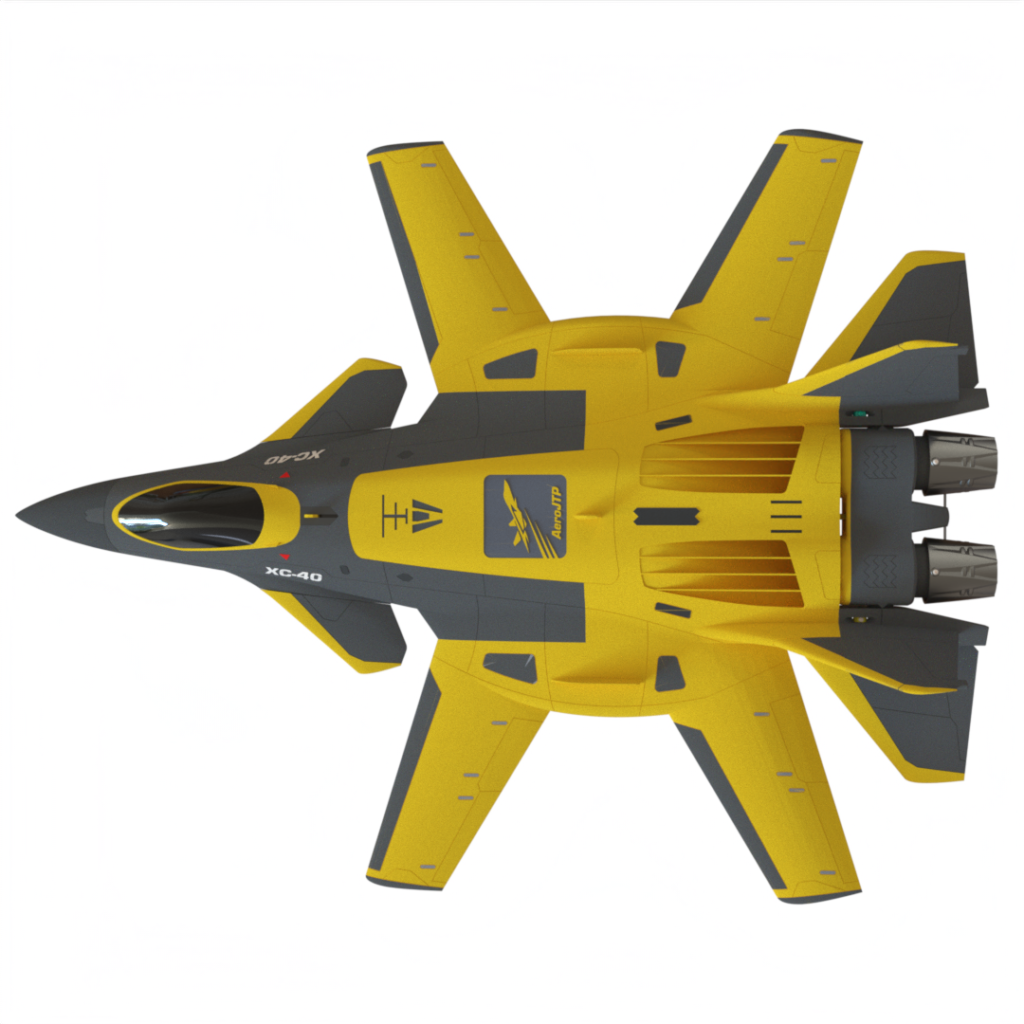
‘The issue with a VTOL jet is that as it lifts vertically you need stability in both the roll and pitch axis,’ says Veenendaal. ‘The closer those fans are to the centre of the jet, the less control you have, so that’s why we made a large central body to accommodate, keeping the fans as far away from each other as possible.’
‘It’s a very unconventional airframe because it’s the first time we built a jet with no front intakes, so there’s minimal disturbance to the flow,’ highlights Veenendaal. ‘The two 40 mm electrically ducted fans [EDF’s] at the rear tilt to provide vector thrust and air feeds through the top via two intakes at the back. The engines can also take air from underneath which means we can utilise the space inside for a servo to control the forward canards.’
Meshing the JRM-02XC40 model
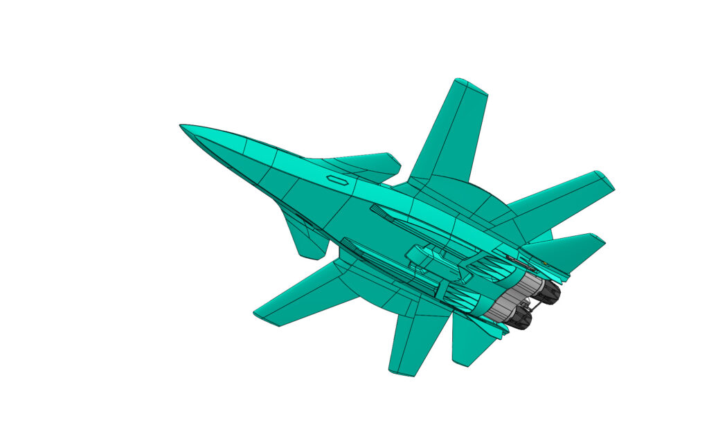
The first stage of the typical finite-volume-based CFD process is to ensure the CAD geometry is of high quality, with no imperfections or inconsistencies that could lead to mesh failure, leaks or inaccurate boundary representations. This CAD clean-up process can take several days or even weeks for very complex CAD geometries. However, the automatic meshing tools provided with HELYX can cope with low quality CAD models as well as detailed geometries, so minimal cleanup and defeaturing is required, yet full layer coverage and low y+ meshing are still achievable.
In the case of the JRM-02XC40, the CAD model was designed in SolidWorks and exported directly into HELYX as a STEP file. ‘It was very straightforward to grab the CAD straight out of SolidWorks, plug it into HELYX and immediately start thinking about meshing, without worrying about the CAD at all,’ explains Schumacher. ‘This particular model is quite complex with thrust vectoring, forward canards and several moving parts, but these were all easily defined in HELYX in accordance with the necessary reference frames.’
Using reference frames in HELYX to manage angle of attack sweeps and modifying CAD configurations
Aerodynamic efficiency plays an important role in UAV performance as the more efficiently a drone can move through air, the less energy it consumes and the longer its flight range. This has become increasingly important with the rise in electric UAVs where current battery technology is limiting range and therefore the potential of such aircraft.
An important measure of aerodynamic efficiency is the lift-to-drag ratio which is indicative of the thrust required to overcome drag in order to generate enough lift. To investigate these characteristics, aerodynamicists usually test or simulate how the UAV’s lift and drag change with different angles of attack. It is also important to understand the onset of the stall condition when increasing the angle of attack to within critical values.
‘There are a couple of ways to approach this in CFD,’ highlights Schumacher. ‘You can modify the CAD and re-mesh for each angle, but this can be time consuming. Or you can keep the same mesh and adjust the boundary conditions to change the incoming flow.’
‘HELYX has a reference frame feature which allows the user to define how the model is orientated in relation to the flow,’ adds Schumacher. ‘The angle of attack sweep can then be realized by simply changing the orientation of that reference frame. This can be prescribed to change with iteration, allowing the user to conduct the full sweep in just one CFD simulation. Furthermore, nested reference frames can be defined for moving parts like control surfaces or thrust vectoring, which makes changing configurations very straight forward.’
Validation and verification of UAV aerodynamic CFD simulations
To first test and verify the existing CFD methods and capabilities available in HELYX to simulate UAVs, a set of well-known validation and verification cases ranging from simple 2D profiles (like the NACA-0012) to more complex full aircraft cases (like the Cessna 210) were defined. The results of these tests confirmed that the accuracy, robustness and speed achieved with HELYX makes it an ideal CFD software solution for this type of applications.
The solver of choice was the pressure-based, block-coupled solver provided with the HELYX-Coupled add-on. In this regard, Schumacher explains that ‘Low Mach number compressible flows have been the bread and butter for CFD for over 40 years now. It comes down to a clever choice of turbulence model and the meshing strategy of the surface. In terms of solver, the HELYX-Coupled add-on solver is our natural choice because it runs fast, it’s extremely robust and converges in less than 100 iterations. So overall, I wanted to test the setup phase for a drone CFD simulation, and it turned out to be quick and simple.’
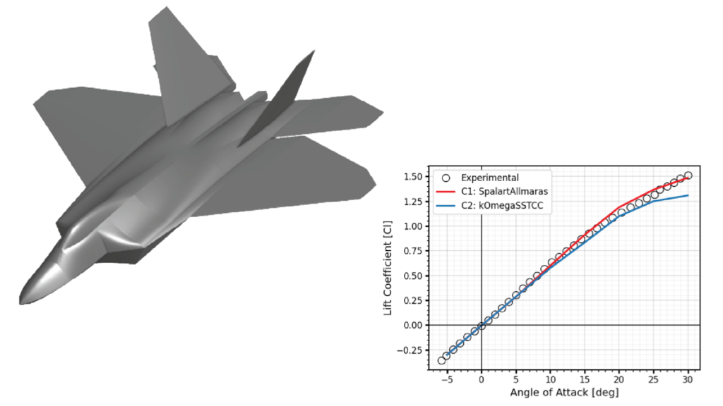
HELYX was also tested with a more recent example, the SSAM-Gen5 validation case, which is based on the F-22 Raptor. The original dataset for this model includes wind tunnel data for several angles of attack at low Mach numbers. Again, the CFD results showed excellent correlation with the experimental lift and drag curves, as shown in the image below.
Simulating the JRM-02XC40 in flight
Once confirmed that HELYX could deliver highly accurate CFD solutions for UAV applications, ENGYS proceeded to simulate the AeroJTP jet in flight. The JRM-02XC40 model was first set up for a level flight at 30 m/s to get familiar with the somewhat unusual configuration of this drone.
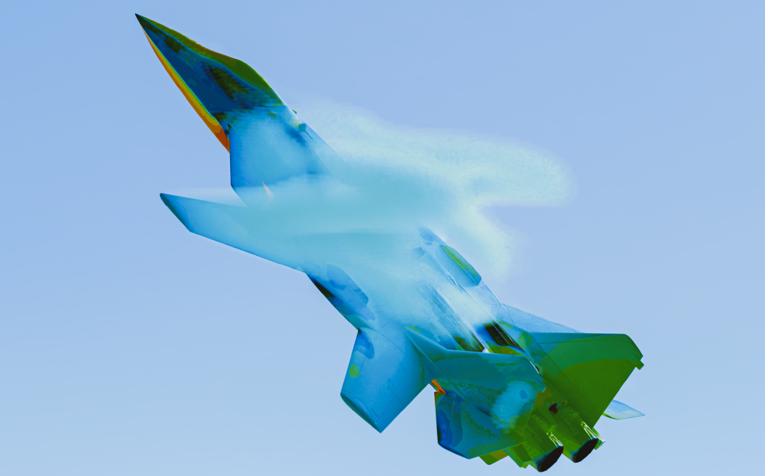
Next, a fully transient simulation featuring a mesh with 39 million cells was performed to assess the flow field at an extreme angle of attack (35 degrees) and very low speed (4 m/s). This simulation made heavy use of nested reference frames to adjust the orientation of all the control surfaces and thrust vectoring CAD.
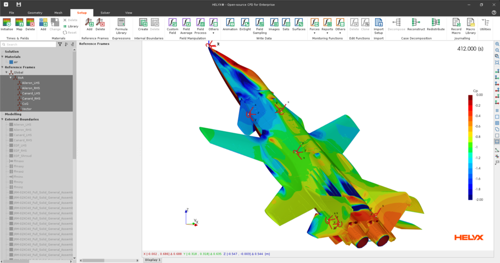
All CFD simulations were set up and completed using the HELYX GUI. ‘We have developed the HELYX GUI to make CFD as easy as possible for our customers,’ says Schumacher. ‘You still need to understand the CFD process, but our GUI means you don’t need to know C++ code or Linux Shell. We want customers to plug in their UAV, set up, mesh, solve and visualise results all in one go within an easy to use, intuitive interface.’
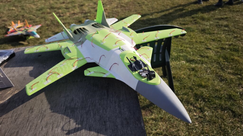
Finally, the CFD results of the JRM-02XC40 obtained with HELYX were compared to real-world flight tests. ‘When running the simulations, I suspected the combination of the forward swept wings, canards, backward swept wings and rear ailerons would make this aircraft inherently unstable,’ reveals Schumacher. ‘But we knew that AeroJTP had successfully flown this aircraft at high angles of attack. To our surprise, the simulations showed the model was extremely stable as the interaction between all the different surfaces develops highly complex vortex structures that stabilise each other. In fact, it was so stable we almost didn’t bother making any animations because it looked like nothing was happening!’
‘We were also surprised that our design was so stable, which was later validated by the CFD,’ agrees Veenendaal. ‘We attached wool tufts to the surface of the wings, and they were so stationary, even at high angles of attack, we had to check they weren’t accidentally stuck down!’
‘The beauty of CFD though, is the visual representation of the pressure zones,’ continues Veenendaal. ‘These clearly showed some turbulence issues which matched our gut feel about the design. So overall, we were impressed that HELYX had not only managed to simulate such a complex aircraft in a short space of time, but also that the results showed excellent agreement with our flight tests.’
References
[1] Z.D., 2025. Big Drones: An In-Depth Guide[Online]. UAV Coach.