The typical range of a fully charged Electric Vehicle (EV) is approximately 100 to 300 miles (161 to 483 kilometres) [1]. To increase this range further whilst minimising the number of charging stops during a journey, manufacturers are exploiting every opportunity to improve efficiency. Whether it is the powertrain, weight or aerodynamics, the more efficient an EV is, the further it can travel on a single charge.
Aerodynamics and Automotive Design
For Internal Combustion Engine (ICE) vehicles, manufacturers focus on optimising drag and lift to improve aerodynamic performance and therefore fuel economy. However, for EV’s it is more important to reduce drag as this means less energy is required to travel the same distance, increasing the range.
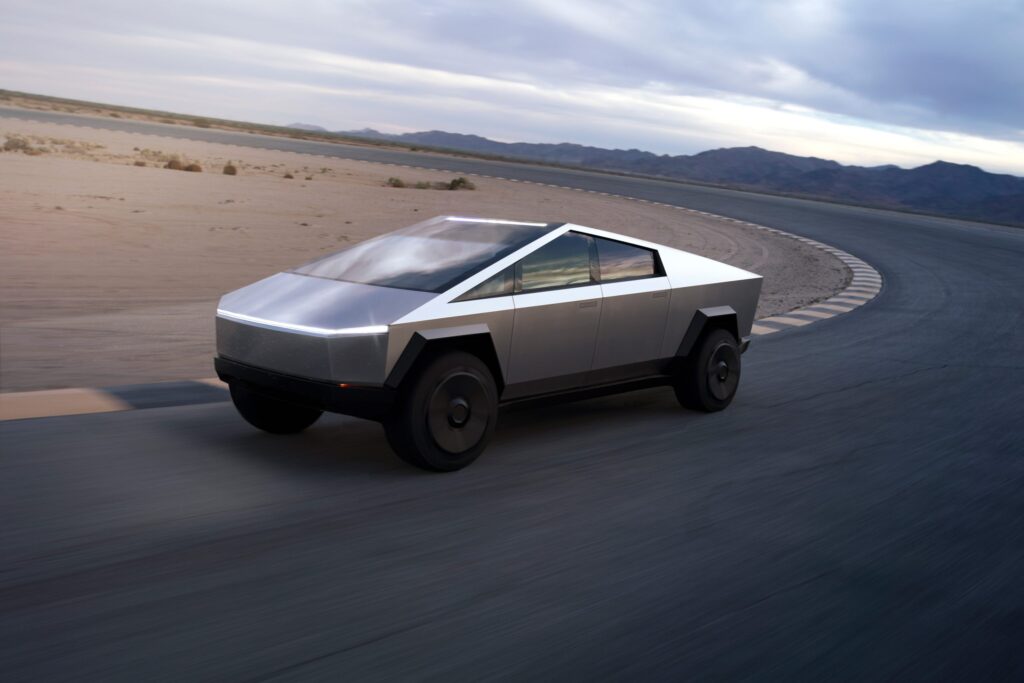
Unfortunately for aerodynamicists, aesthetics has historically been the priority for manufacturers as this is what primarily sells cars. Now however, consumers want EVs that can travel long distances on a single charge, shifting the focus to aerodynamic efficiency. This can lead to conflict between aerodynamic and design departments.
The relationship between aerodynamicists and the design studio can often be demanding,’ highlights Angus Lock, General Manager at ENGYS North America. ‘There is a compromise between aerodynamic performance and aesthetics. Therefore, it is important to communicate with designers in a language they understand whilst also appreciating where they are coming from. CFD [Computational Fluid Dynamics] can be a useful communication tool to help styling departments and aerodynamicists work together.’

Communicating Through CFD
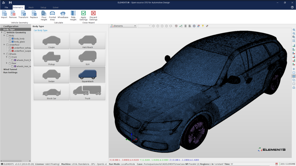
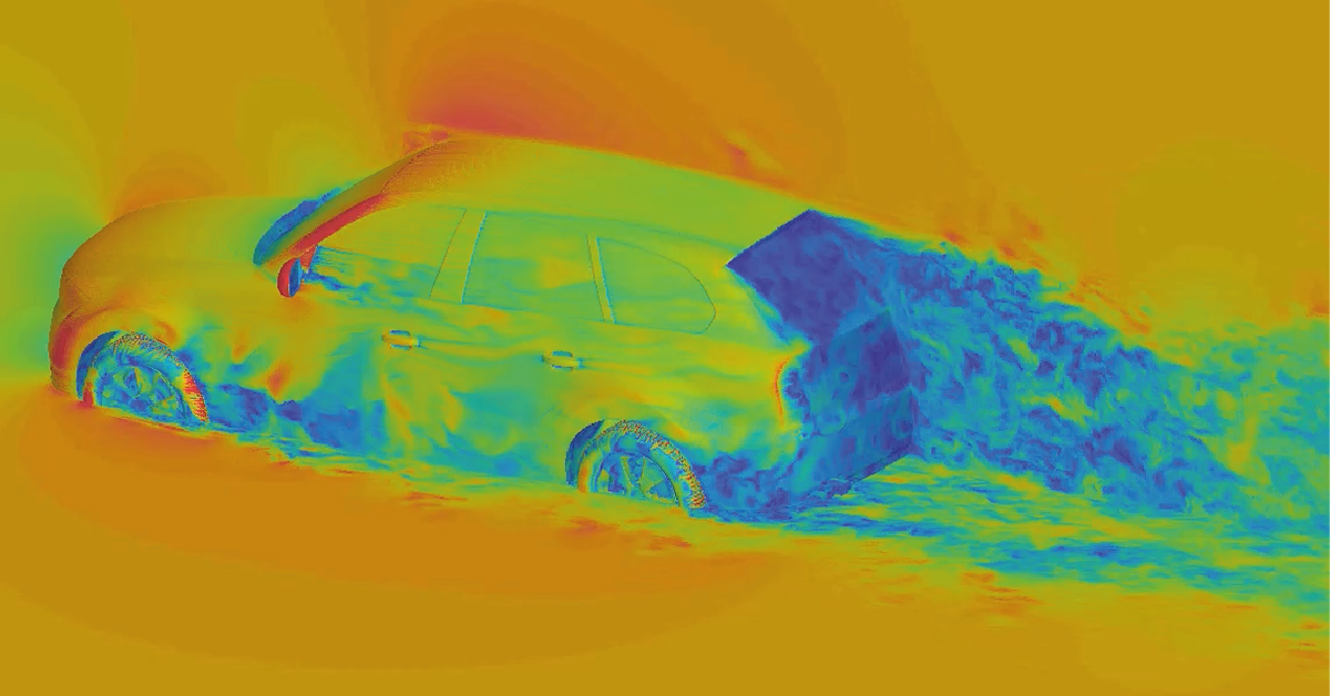
CFD simulates complex air flows around a vehicle and analyses how different surfaces and features affect drag, lift and aerodynamic efficiency. However, it is often difficult to fully understand why a particular design change leads to an aerodynamic affect. To help bridge this gap, CFD tools such as ELEMENTS can output contour maps, streamlines and pressure plots. This not only helps aerodynamicists to visually understand the flow structures, but designers too.
‘With over 30 year’s experience of using CFD in automotive design, I have a good understanding of where I need to make changes to gain aerodynamic performance,’ says Lock. ‘But CFD visualisations help me explain my reasoning behind those changes. Designers are visual learners so having multicoloured plots and animations can be extremely powerful when communicating how styling changes affect aerodynamics.’
How CFD Can Accelerate The Design Process
The latest high performance computing along with open source CFD software allows multiple CFD simulations to run simultaneously on unlimited cores. Consequently, manufacturers no longer have to wait for the results of costly full scale wind tunnel or track tests. Instead, CFD can be used to understand the aerodynamic performance of initial concepts much earlier in the design process. This helps catch any major issues early, but also avoids making design changes further down the line, which are more difficult to implement.
➨ Find out how open source software can boost your CFD capabilities.
‘Often aerodynamicists don’t see the vehicle design until the first 3D surfaces are released to the wider organisation. By this time the design team already know what they want the vehicle to look like,’ says Lock. ‘This makes it harder to make any fundamental changes. However, if you can consult them during the initial phase, it is easier to build any aerodynamic constraints into the design.’

As well as using CFD to identify the areas that are critical to performance, it can also be used to highlight areas that are not. This gives designers the freedom to implement more drastic styling ideas in areas which are not fundamental to performance.
Easier CFD Set-up
One of the biggest hurdles to adopting CFD is understanding how to accurately set up a simulation. Specifying the right boundary conditions, mesh size and turbulence models to achieve reliable results can be overwhelming for new users. While supporting documentation is often riddled with confusing technical jargon.
To help aerodynamicists without in-depth CFD knowledge conduct a full CFD analysis, ENGYS have provided standardised CFD simulation templates within its software. These templates define characteristics such as mesh settings and solver parameters that are based on real world data. Each template is tailored to a specific type of vehicle and wind tunnel.

‘It helps users have a starting point,’ explains Lock. ‘They don’t have to use the exact settings within a template, but once the geometry is imported, ELEMENTS walks the user through the entire set-up process. So you don’t have to be a CFD engineer to generate accurate CFD results. It also means that aerodynamicists can focus on optimising aerodynamic performance rather than the reliability of CFD simulations.’
New CFD Technologies
As computing power has continued to grow over the last few decades, so has the capabilities of CFD. Automatic meshing, turbulence models and adjoint optimisation are just some of the latest innovations that are transforming CFD.
‘Adjoint optimisation is one of the most exciting CFD technologies around at the moment,’ reveals Lock. ‘It’s the first time that software can show you areas of the car to improve, that you may not have thought of.’
Adjoint is a topology optimisation technique based on the adjoint method. It essentially identifies what changes are required to an input to achieve the desired effect on the output.
For example, instead of each CFD calculation predicting how a single design change influences every aspect of the flow. The adjoint method predicts how every design change influences a single aspect of the flow. Once a clear objective is set, such as reducing aerodynamic drag, and the relevant areas of the geometry are defined, adjoint automatically iterates until the optimum solution is found.
The results from adjoint optimisation studies are another effective tool to explain the aerodynamic implications of changes in geometry. ‘You can show designers the results and it is clear that the areas in blue highlight opportunities where we can go inwards from the surface. While the areas in red are where we can extend the surface outwards. It helps them understand where they can have more freedom.’
Even with the best communication tools and practises, maintaining a collaborative relationship between aerodynamicists and designers can still be a challenge. However, if achieved, the rewards can be invaluable.
‘At a previous company, I was involved in a project that had a drag coefficient [Cd] of over 0.3. At the time, the relationship between the aero and styling departments was strained,’ highlights Lock. ‘This was partly due to aerodynamicists requesting changes when the design was nearly finalised.’
‘However, after using CFD to explain the aerodynamic benefits of these changes, we began to build a relationship with the designers. By the end of the project we managed to get the Cd down to 0.25. This is just one example, but it proved that effective collaboration between aerodynamics and design can lead to a stylish yet aerodynamically efficient vehicle.’
References
[1] Electric vehicle range – how far can I drive in an EV? [Online]. RAC.
[2] Lambert, Fred. [2022]. Tesla Cybertruck electric pickup surprises in aerodynamic performance simulation [Online]. Electrek.


