Polyurethane or short PUR or even shorter PU is impossible to avoid in our modern life. Since its discovery in the late 1930’s in Leverkusen it has been used for countless purposes. In its foamed-up form it is insulating our houses and refrigerators, it lets us sleep soft and comfortable at night and is used as a core material in vehicles, to name a few applications.

For the industry it is therefore necessary to understand and if possible, optimize or adapt industrial processes involving the manufacturing of parts and products made out of PU foam to ensure high quality and desired material properties.
ENGYS, in collaboration with an industrial partner, has developed a CFD solver to simulate the complete process of foaming polyurethane from injection of the reagents into a mold all the way to the final shape. Marrying existing technologies within HELYX-CFD, like the Generalized Internal Boundaries (GIB) for treating dynamic injection and mold closing, to a new solver to tackle the intricacies of the chemical reactions involved, led to a foaming simulation process with unique capabilities.
Technology
The foaming simulated process can be divided into three distinct phases.
- Phase 1 involves the injection or pouring of the mixture into a mold. The process needs to be fast, as the mixture is starting to react and foam up after a short while. During this process it is important to ensure that the mixture is distributed in a way to ensure desired (usually uniform) material properties after the foaming process is done and that the whole of the mold is filled up in the end. Being able to simulate the effects of different techniques and injector paths on the final product saves countless laboratory hours. We use the existing GIB technology to have complete freedom of movement for the injector nozzles in the domain.
- Phase 2 involves the closing of the mold. Again, we use GIB to close the lid. In this phase the closing lid may push the liquid mixture out of its way. In addition, the foaming reaction has started, increasing the volume of the mixture and interacting with the lid closing. In reality, small venting holes are present to allow trapped air to evacuate. Once the foam reaches those venting holes they are usually closed mechanically. Again, timing the mechanical closing of those holes usually requires a trial and error process in a laboratory. We have implemented a special boundary condition to allow air to be vented and closing the mold once the foam reaches the venting opening. The exact time that has to happen can then be extracted from the results and applied to the production process.
- Phase 3 has the chemical reaction in full swing, drastically increasing the volume of the foam while reducing density and increasing viscosity. The required chemical reactions are modelled and concentrations of the reagents can be tracked and analyzed. A simpler method to model the foaming process is a prescribed density and viscosity behavior over time. Both options are available. Once the foaming process comes to a halt, the final form can be analyzed to see whether trapped air pockets are present or whether the density of the final foam is uniform throughout the product. Changes to the injector path might be required to improve the results.
Foaming Simulation Demonstration
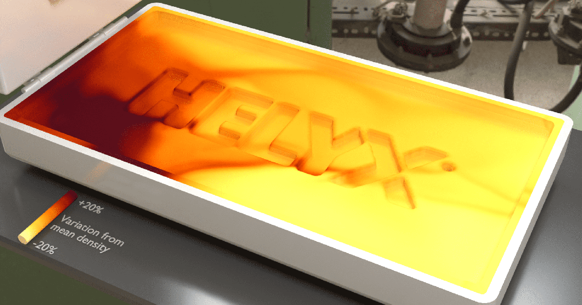
Using a fictitious mold geometry and the previously mentioned prescribed density and viscosity behavior method,the whole simulation is shown in the animation below.
At first the injector moves in and distributes the mixture. While the lid closes, the mixture settles and starts reacting. Once the lid is closed (made transparent here for visualization purposes) the reaction starts in earnest, and fills up the mold. As the mixture/foam decreases its density by an order of magnitude, a relative color scale is shown, coloring the foam according to density variations from its current mean density. The final form is then showing regions where the density is higher or lower, i.e. the cushion is harder or softer.
Contact us to learn more about the foaming simulation capabilities for PU foaming and how you can use HELYX-CFD to optimize your processes.


