Skin friction drag can account for up to approximately 30 to 40% of the total aerodynamic drag of a streamlined vehicle [1] and around 45% in subsonic aircraft [2], to name a couple examples. This is why accurately capturing the physics of the boundary layer in Computational Fluid Dynamics (CFD) is critical for determining realistic drag predictions, as well as other wall-dominated flow phenomena such as thermal flows, film modelling, etc. Modelling these specific problems requires high quality, body-fitted, low-y+ finite volume grids with complete coverage of the boundary layer, which can be difficult to achieve with conventional automatic meshing algorithms. In this article we discuss the various mesh methods available in HELYX to tackle the low-y+ mesh challenge.
Meshing Algorithms in HELYX
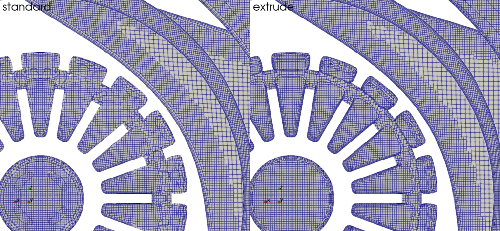
HELYX currently offers two fully automatic, hex-dominant, meshing algorithms, each one providing a distinct approach for generating near-wall layers. The first method, known as the Standard Mesh algorithm, prioritises mesh quality over near-wall layer control, delivering maximum robustness when meshing highly complex geometries. The second method, referred to as the Advanced Mesh algorithm, provides users with full control over near-wall layer creation and ensures complete coverage of all surface patches in the model, but it restricts certain quality metrics in regions distant from the walls to accommodate the near-wall mesh insertion.
The Standard Mesh algorithm is a reliable and highly robust meshing approach, often chosen for CFD simulations where low-y+ requirements are not necessary, particularly when dealing with complex geometries with intricate topologies. The algorithm initially creates a hexahedral background mesh that roughly conforms to the geometric domain by adding and removing cells where needed. This mesh is then refined at surface and volume level based on user inputs, after which the relevant grid nodes are projected to the surface patches – in a process known as “snapping” – and the resulting cells are optimised until the final grid is correctly aligned with the underlying geometry. Finally, near-wall layers are inserted to conform to the nearby surface and volume elements of the final grid based on a series of user-defined near-wall layer controls, such as number of layers, first cell height, expansion ratio, etc.
Andrew Jackson, Head of Development at ENGYS, explains in relation to the Standard Mesh algorithm that: “if the mesh layers cannot satisfy the quality settings defined by the user, particularly around complex geometry, the layers will collapse locally. This collapse might create a lack of boundary layer resolution, which can potentially result in a loss of physical modelling accuracy for certain cases.”
Similarly, Matteo Limongelli, co-founder at NOPE Engineering, a consultancy who recently switched to HELYX, explains: “Often, the parts of the mesh that the Standard Mesh algorithm struggles to cover are the most geometrically complex and therefore where you need the solution to be extremely accurate. You also have limited control over the extrusion of the boundary layer cells. This means that sometimes you end up with elements that are not of high quality and there’s not much you can do about it.”
ENGYS Advanced Mesh Algorithm
To help resolve the near-wall layer control limitations of the Standard Mesh algorithm described above, ENGYS developed the Advanced Mesh algorithm to offer an alternative meshing solution for creating proper low-y+ CFD grids with full coverage on all relevant wall patches.
The Advanced Mesh algorithm still relies on the same principles of the Standard Mesh approach to create the hex-dominant base grid and accurately project the cell nodes to the correct surfaces of the geometry during the snapping phase. However, the near-wall layer insertion process is fundamentally different.
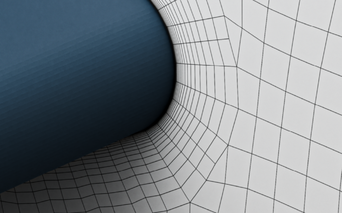
The Advanced Mesh algorithm creates a one cell buffer layer by extruding the surface elements to unit aspect ratio using a sphericity optimisation objective function. During the snapping phase of the meshing process, this single layer of cells is projected to the surface and then stretched in the normal direction out to the far field, at which point it can be split into many layers based on the user requirements. The result is a low-y+ grid with the preferred number of layers, first cell height and expansion ratio for accurate modelling of the boundary layer.
“It’s a bright idea because by definition it guarantees 100% cell extrusion and therefore full coverage of the boundary layer,” adds Limongelli regarding the Advanced Mesh algorithm. “The optimization process then automatically improves the mesh quality so all you have to do is fine tune the mesh in the far field – you don’t need to spend hours optimizing the mesh in the near wall region.”
“The meshing process can be a bit slower than the Standard Mesh approach, but the number of iterations to reach a high-quality mesh is far fewer than other meshers,” continues Limongelli. “This saves significant time when setting up a CFD simulation which means you can run more configurations, so your final design is likely to have higher performance and you have more confidence in your results.”
How the Advanced Mesh Algorithm is Helping NOPE Engineering
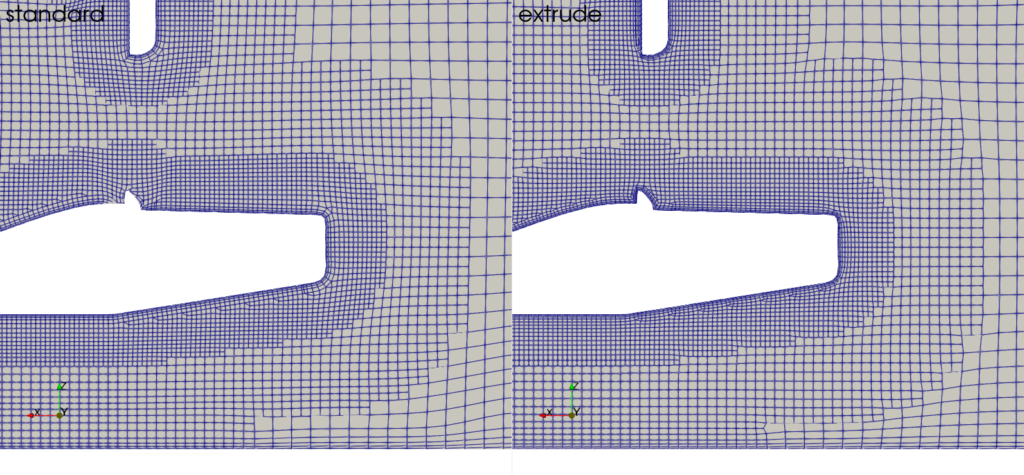
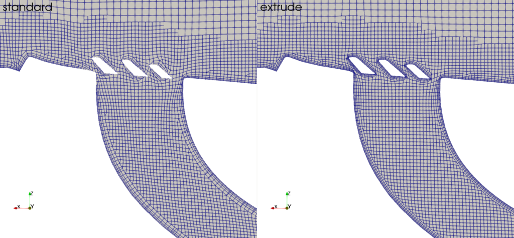
To prove the effectiveness of the Advanced Mesh algorithm developed by ENGYS, several comparison studies have been conducted. These studies highlight how the alternative Advanced Mesh algorithm achieves complete boundary layer coverage compared to other meshing tools, as well as simulation results that correlate more accurately with experiments.
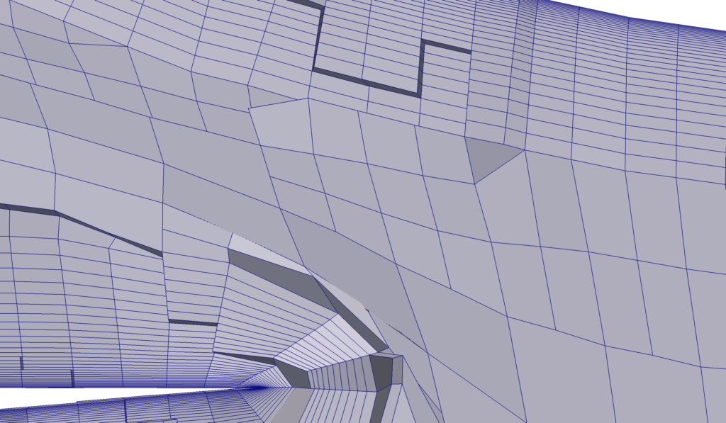
Exploiting the full potential of the Advanced Mesh algorithm requires a few best practises. One very important requirement is to ensure that the surface mesh refinements selected by the user are enough to properly resolve the underlying geometry. Failure to accomplish this might result on poor quality surface patches which can preclude the mesh optimization process, particularly around sharp edges where layer quality can quickly deteriorate.
“There is a lot you can do with the Advanced Mesh algorithm, and the customer support team at ENGYS are great at showing you how to fully utilise the software,” highlights Limongelli. “You can share cases with them, and they will feedback with modified entries in the case dictionaries so you can understand how to best set up your specific case – it’s an efficient way to transfer knowledge.”
“But what I am most impressed with is how HELYX is a research code that has been transformed into an industry code,” concludes Limongelli. “Other CFD packages are incredibly robust, but they sacrifice mesh quality and accuracy to ensure a solution is always achieved. Whereas ENGYS have taken a highly accurate research code and added processes and functionality on top to make it suitable for industry. This means it is easy to use and reliable, but you benefit from the highest levels of accuracy too.”

References
[1] W.H., 1998. Aerodynamics of Road Vehicles, 4th Edition.
[2] M.F., R.A., 1974. A general review of concepts for reducing skin friction, including recommendations for future studies [Online]. NASA Technical Memorandum TM X-2894